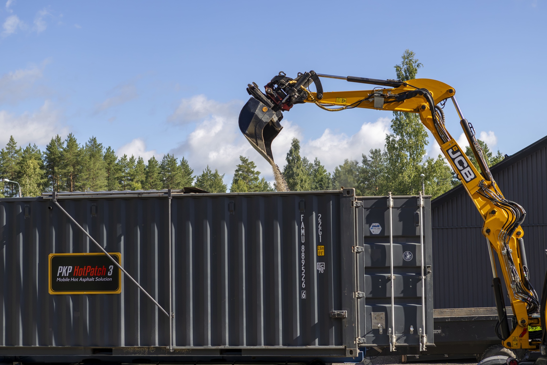
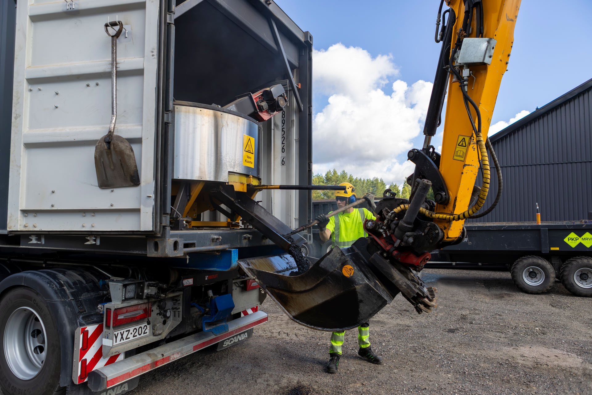
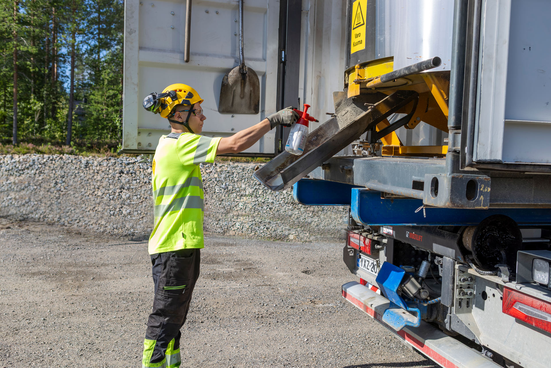
Kiviaines ja bitumi lastataan konttiin.
PKP HotPatch 3
PKP HotPatch 3 on konttipohjainen mobiili asfalttilaitteisto, joka on kehitetty kuuman asfalttimassan valmistukseen suoraan työmaan tai korjauskohteen läheisyydessä. Laitteisto vastaa tilanteisiin, joissa tavallinen asfalttiasemalogistiikka on hidas, kallis tai epäkäytännöllinen.
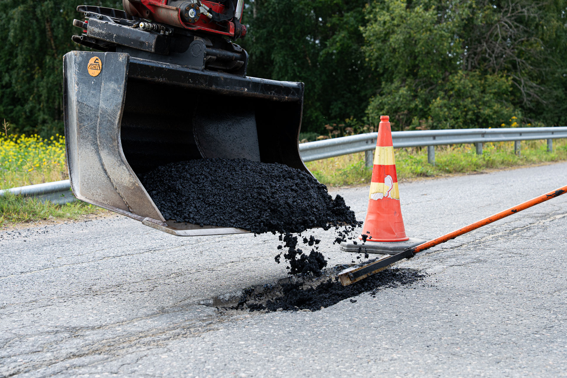
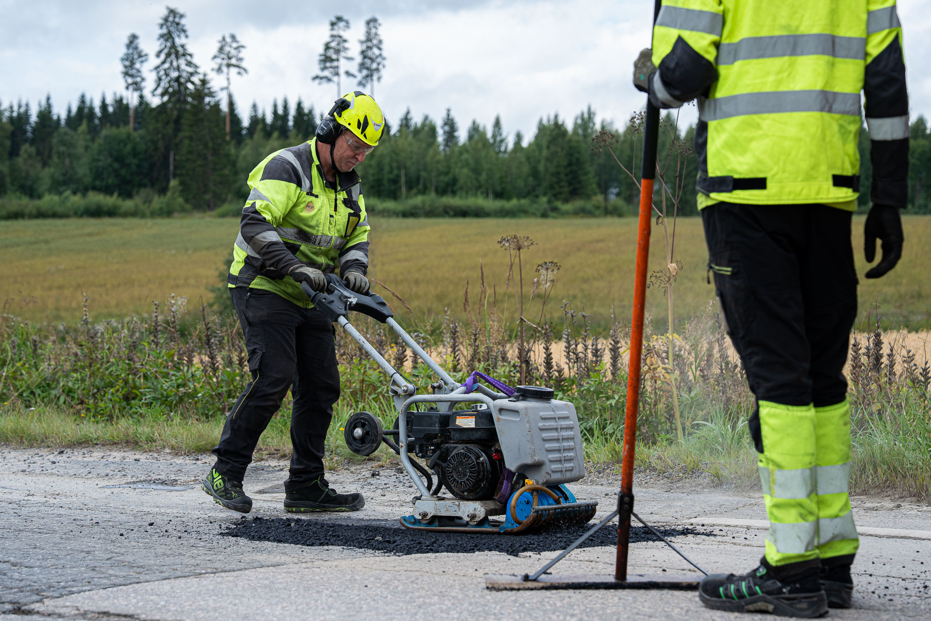
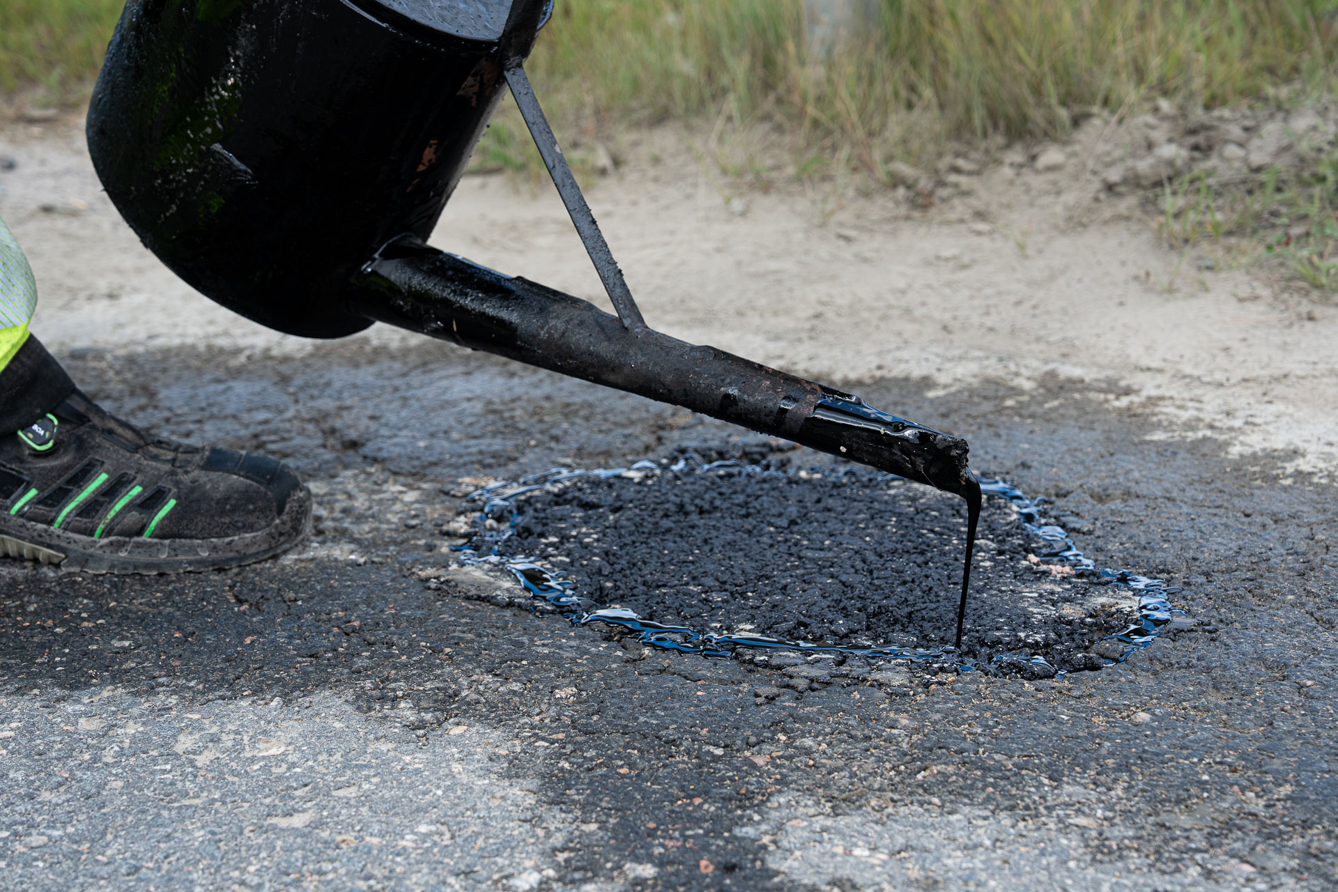
Asfalttipaikkausta suoraan kohteessa
PKP HotPatch 3 on konttipohjainen mobiili asfalttilaitteisto, joka mahdollistaa laadukkaan kuuman asfalttimassan valmistuksen suoraan työmaan tai korjauskohteen vieressä.
Laitteisto on kehitetty poistamaan perinteisen asfalttilogistiikan pullonkaulat: pitkät kuljetusmatkat, korkeat kustannukset ja riippuvuus kiinteiden asfalttiasemien aukioloajoista tai talvisista sulkuaioista. Väliaikaisten ja heikkolaatuisten kylmäpaikkausten sijaan korjaukset toteutetaan heti kestävällä, kuumalla massalla.
Laitteisto on kehitetty poistamaan perinteisen asfalttilogistiikan pullonkaulat: pitkät kuljetusmatkat, korkeat kustannukset ja riippuvuus kiinteiden asfalttiasemien aukioloajoista tai talvisista sulkuaioista. Väliaikaisten ja heikkolaatuisten kylmäpaikkausten sijaan korjaukset toteutetaan heti kestävällä, kuumalla massalla.
Keskeiset teknologiat
- Konttipohjainen mobiili rakenne
- Kiviainesjärjestelmä
- Bitumin lämmitys ja kierrätys
- Sekoitin
- Punnitus / annostelu
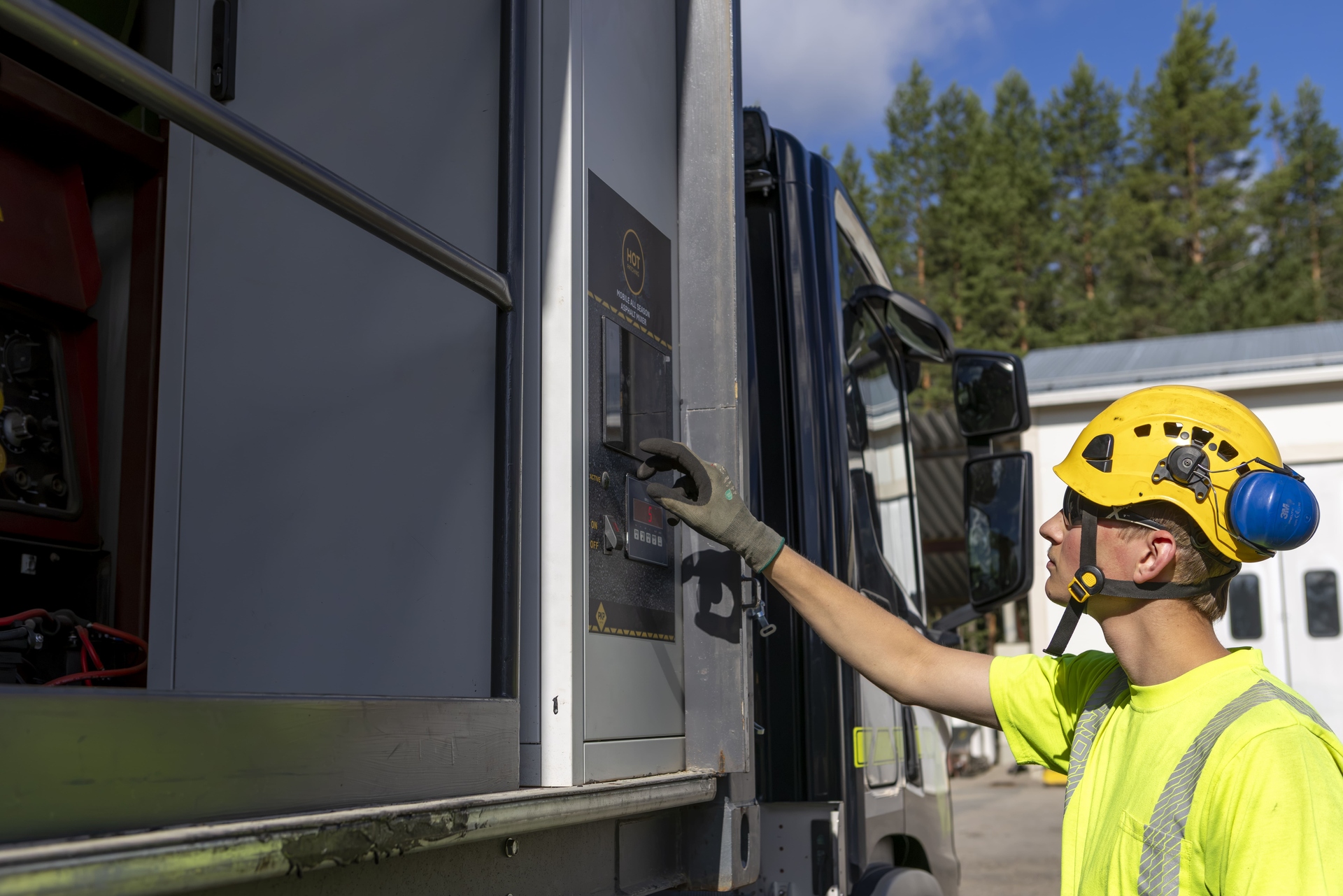
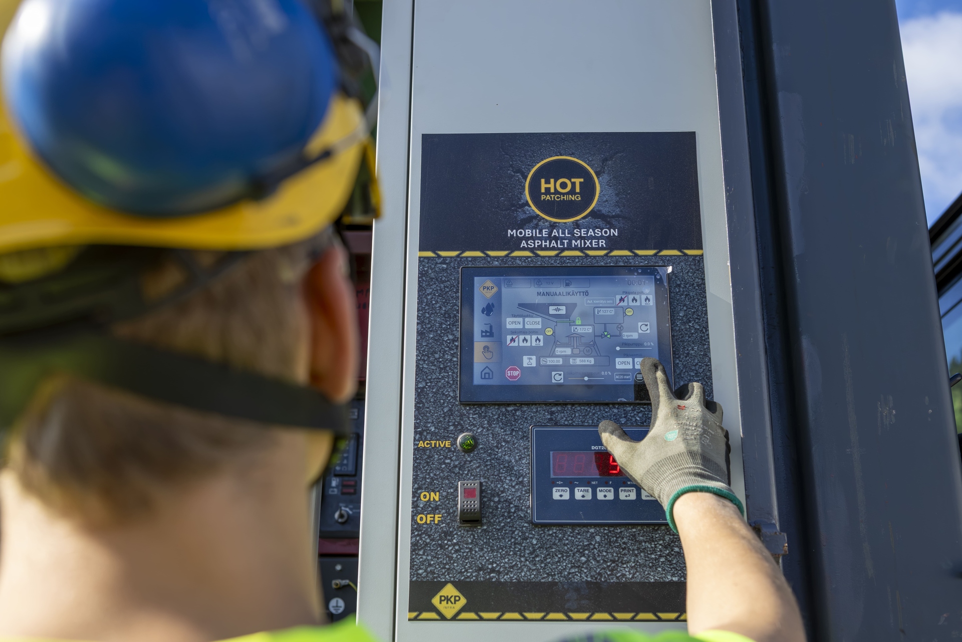
- Ohjausjärjestelmä
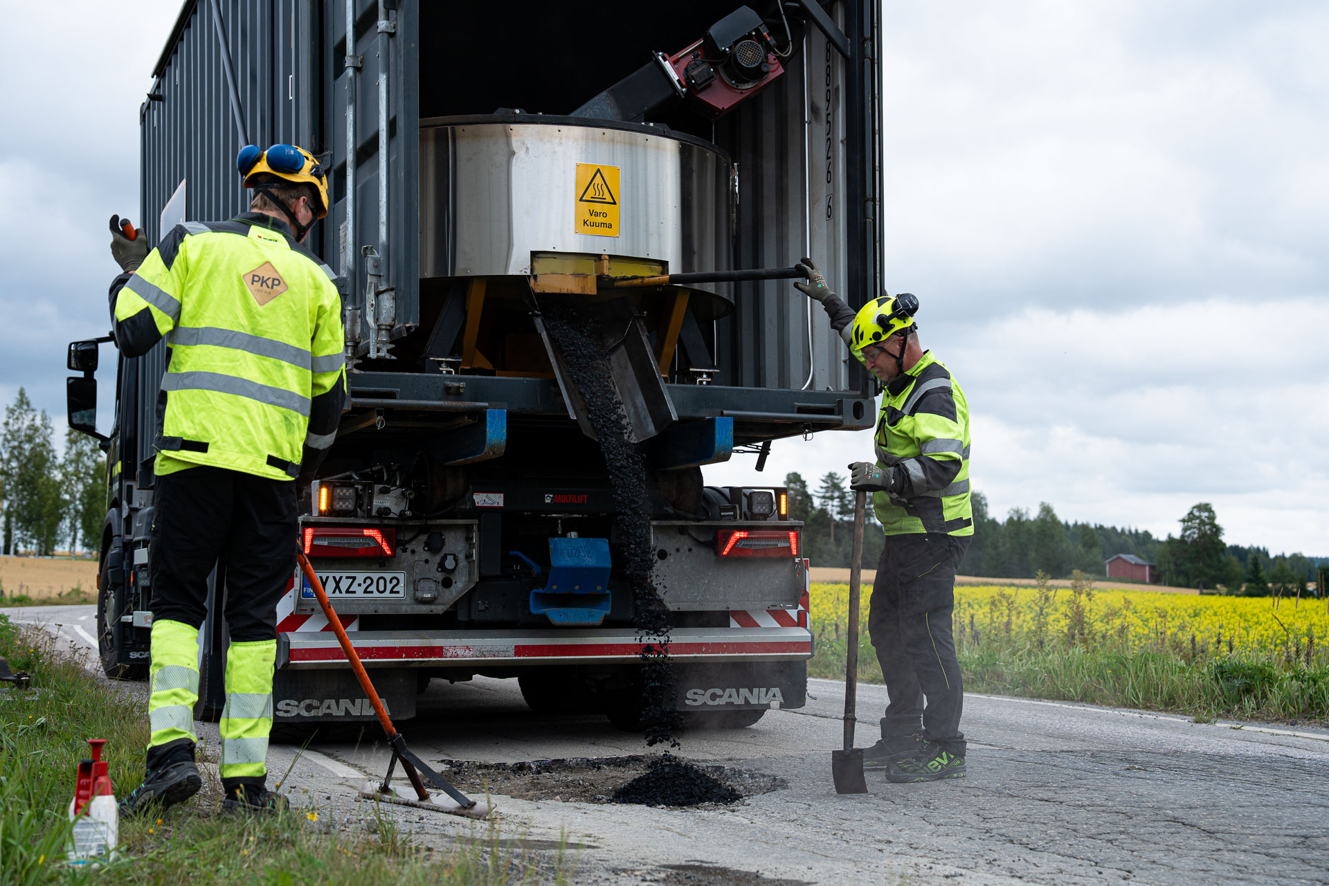
- Kuuman massan purku
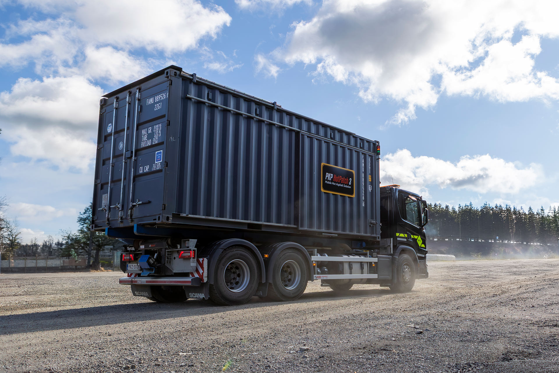
- Kuljetettavuus ja työmaakäyttö
Soveltuvuus ja käyttökohteet:
- Maantie- ja katukorjaukset
- Lentokentät
- Teollisuusalueet
- Satamat ja terminaalit
- Yksityistiet ja syrjäiset kohteet
- Kriittinen infrastruktuuri
Laitteisto soveltuu käytettäväksi myös haastavissa sää- ja talviolosuhteissa.
Keskeiset hyödyt:
- Kuuma massa lähellä korjauskohdetta — Vähentää riippuvuutta kiinteän asfalttiaseman sijainnista.
- Sopii pienempiin paikkausmääriin — Mahdollistaa järkevämmän toiminnan silloin, kun täysi asfalttikuorma ei ole tarkoituksenmukainen.
- Liikkuva ja joustava ratkaisu — Soveltuu kohteisiin, joissa paikkaustarve vaihtelee ja etäisyydet voivat olla pitkiä.
Näin PHP HotPatch toimii
Tutustu PKP HotPatch -laitteistolla toteutettavan asfalttipaikkauksen vaiheisiin.
Tekniset tiedot
Lataa Data sheet (pdf)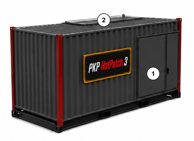
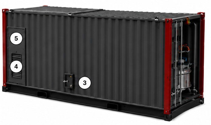
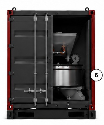
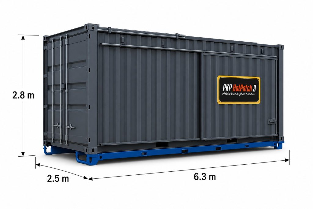
Ulkoa
| Nro | Komponentti | Toiminto |
|---|---|---|
| 1 | Oikea sivu | Sivuluukku / sivun huoltoaukko. |
| 2 | Katto | Liukuva kiviaineksen täyttöluukku. |
| 3 | Vasen sivu | Luukku, josta pääsy kuuman bitumin juoksutushanaan. |
| 4 | Vasen sivu | Moottorin jäähdytysaukot. |
| 5 | Vasen sivu | Dieselgeneraattorin huoltoluukku. |
| 6 | Takaosa | Takaovet ja asfaltin purkualue. |
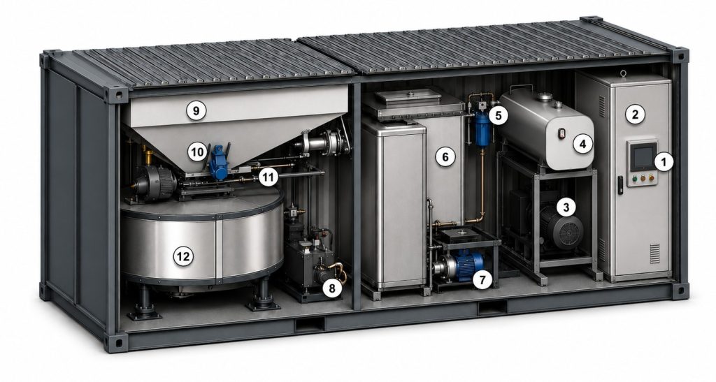
Sisältä
| Nro | Komponentti | Toiminto |
|---|---|---|
| 1 | Käyttö- / ohjauspaneeli | Prosessinohjauksen pääkäyttöliittymä. |
| 2 | Sähkökeskus | Sähkö- ja ohjausjärjestelmän komponentit. |
| 3 | Dieselgeneraattori | Tuottaa yksikön tarvitseman sähkötehon. |
| 4 | Yhteinen polttoainesäiliö | Polttoaine dieselgeneraattorille ja molemmille prosessipolttimille. |
| 5 | Polttimien polttoainesuodatus | Suodattaa polttoaineen ennen polttimia. |
| 6 | Bituminkeitin | Eristetty terässäiliö bitumin varastointiin ja lämmittämiseen. |
| 7 | Bitumipumppu | Pumppu bitumin kierrätykseen ja siirtoon sekoittimeen. |
| 8 | Hydrauliikkayksikkö | Sähkökäyttöinen hydrauliikkayksikkö. |
| 9 | Kiviainessuppilo | Siilo kiviaineksen varastointiin. |
| 10 | Suppilovibraattori | Avustaa kiviaineksen virtausta. |
| 11 | Kiviaineksen syöttöportti | Ohjaa kiviaineksen virtausta suppilosta sekoittimeen. |
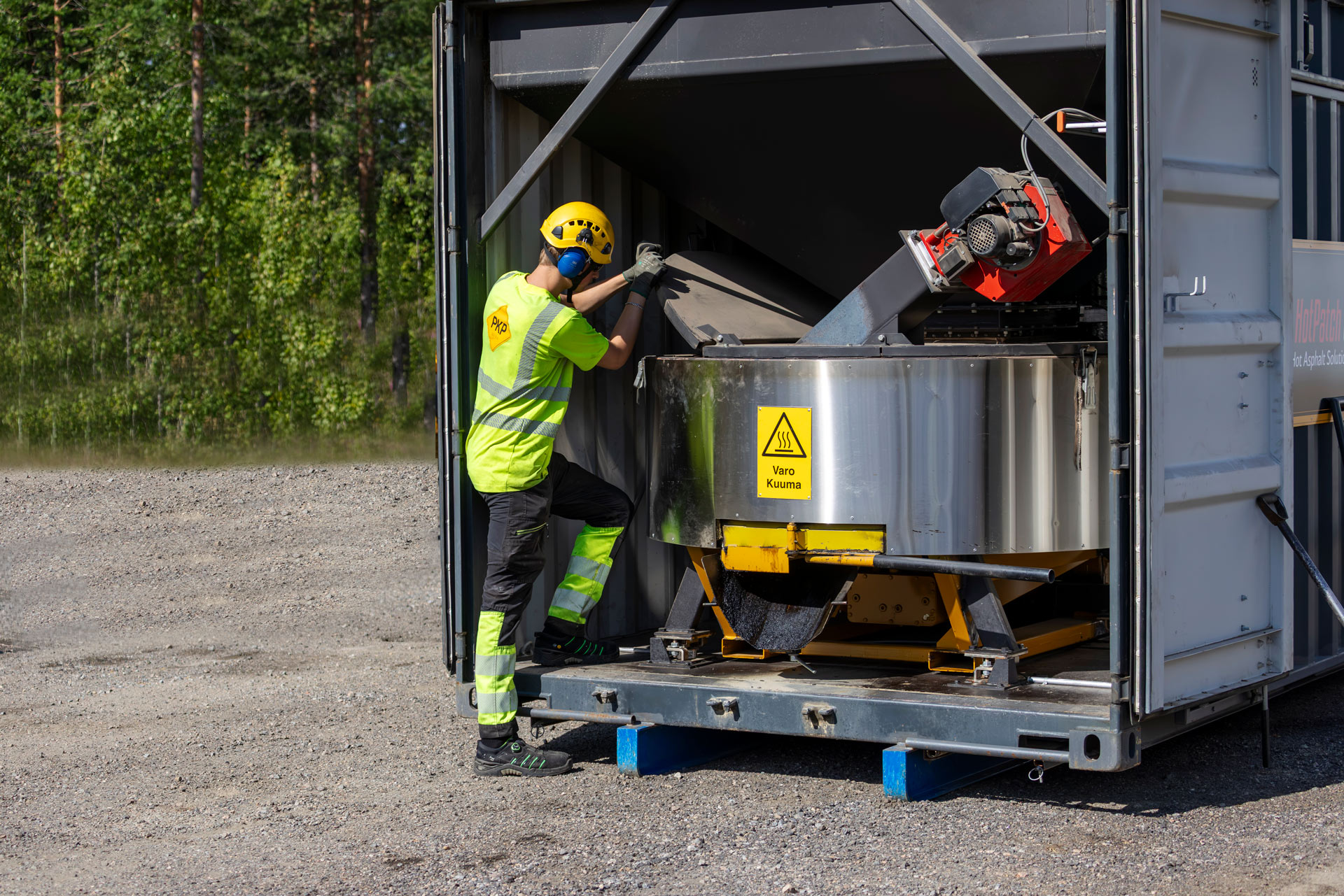
| 12 | Asfalttisekoitin | Sekoitin kiviaineksen kuumennukseen ja asfalttimassan sekoitukseen. |